Creating & mosaicking data cubes
Each stack of reduced fibre spectra is resampled onto a 3D x-y-λ grid (with reference to the MDF extension) using
gfcube:gfcube csteqbpxprgS20140919S0059 fl_atm+ fl_flux+ fl_var+ fl_dq+ gfcube csteqbpxprgS20140919S0062 fl_atm+ fl_flux+ fl_var+ fl_dq+
You should normally enable all of the options. The atmospheric dispersion correction automatically straightens the spectra to about 0.1” or better.
To inspect the cubes, you can give any IRAF task a 1D or 2D image section, eg. to see a single image plane:
display dcsteqbpxprgS20140919S0059[sci][*,*,650] 1
There are also various programs around that can display projections of a 3D cube directly, or you can load one from the DS9 GUI and step through the planes.
Attempt to measure any spatial offsets between the cubes and shift their World co-ordinate systems to reflect those differences (so that features will have the same World co-ordinates in each one). Such offsets can be due to intentional dithering, flexure or re-acquisition on different nights. Any spectral offsets should already have been dealt with during Wavelength calibration or Wavelength flexure correction.
In this particular example, there is no significant difference between the exposures and the following step actually makes things slightly worse for some reason, so can be left commented out:
# pyfalign dcsteqbpxprgS20140919S0059,dcsteqbpxprgS20140919S0062
For nebulous sources, you should specify
method=correlate. If the registration doesn’t work reliably, you can use any available method (eg.imexam) to determine pixel offsets, multiply them by the pixel scale (usually 0.1) and subtract them from the header keywords CRVAL1 & CRVAL2.Resample all the cubes onto the same spatial grid and co-add them:
pyfmosaic dcsteqbpxprgS20140919S0059,dcsteqbpxprgS20140919S0062 dcsteqbpxprgS20140919S0059_add var+
To check the alignment, you can run this command with the
separate+option, which resamples the cubes onto the same grid but in separate FITS extensions, instead of co-adding them (this can also be used to align them prior to more sophisticated co-addition with another program, such asimcombine).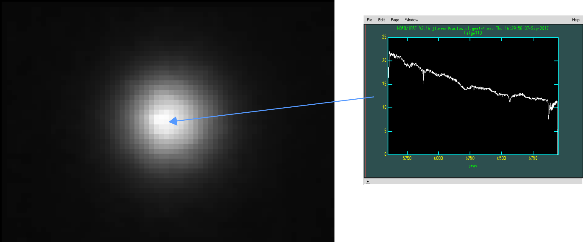
Image of the target star, from a single wavelength plane near the middle of the co-added data cube (left) and the spectrum from the central pixel (right).